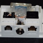
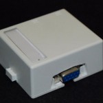
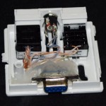
This electronic sensor system is best used with a computer tracking software such as Grand Prix Race Manager (GPRM) by Randy Lisano. My research found this to be the best software for the job and one of the best prices. It makes races run faster and more organized, this makes it more fun. There is a link on the right.
These plans incorporate the Micro Wizard electronics and my own design for the sensor bridge and component location. You can order this system in a kit with just the electronics.
I have previously built them into the base of the track itself or in a project box, many people build them into the finish line over the track like this one.
 I have modified the manufacturers ideas a little by moving some of the connectors to an interface box. The nice thing about this design of the circuit is it allows you to keep the interface box near the computer. Meaning the only long cable you will need is a very easy to find and relatively inexpensive one, a Cat 5 cable (standard computer network cable). It is peanuts compared to a long serial cable and can be found anywhere. The power cable and start switch wire only have to be run 3-5 feet instead of all the way down the track to the finish line.
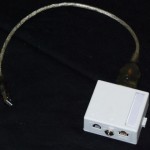 Another nice thing is the adapter box sits right behind my computer so the serial to USB adapter goes from the box the computer. Click any of these images for a closer look.
For those who just like to copy things instead of making decisions about what wire goes where, I have a Wiring connections list.
Constructing the Lane Sensor Bridge
IR LED Mounting- You need to build a frame to suspend the IR LED’s over the track lanes. I prefer the aluminum bridge for it’s low profile and strength and ease of use, but it can be made of wood.
Aluminum Bridge: Use 3/4 inch Channel Top and Bottom and 3/4 inch Square Tube for the uprights.
These pieces can be found at you local Home Depot or Lowe’s etc. You will need LED mounts for this option and your holes will have to be the right size for the mounts you choose. you can also glue them in place with silicone or hot glue. Sections of aluminum are bolted together using 8-32 machine screws and nuts.
Measure the width of your track and where the centers of the lanes are. Cut three pieces of channel to the width of the track plus 1 1/2″ for connection to the uprights. Decide what height above the track you want the bridge then add the thickness of your track as the bottom of the bridge runs under the lane surface and a little extra room in addition to the 3″ you need for the electronics and cut the uprights. Most organizations have a max height of 3″ for their cars so 8″ uprights should do nicely.
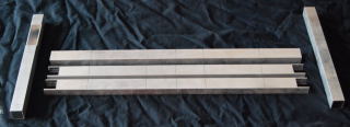 Cut the ends of the lower and middle channel to allow the uprights to fit into the sides. Drill holes for the bolts. Also drill holes for the wires in one upright allowing for plenty of room.
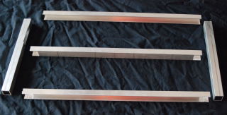
 Make sure to stack the aluminum channel used for the IR LED’s and the Photo transistors together and then mark the holes across all pieces at once. This way the holes will line up properly, but care should be taken to drill the holes perpendicular to the material. Use a drill press or a drill with a built-in level.
Insert the LED’s into the mounts (if you are using them) and snap into place in the channel. Use silicone or hot glue to secure them in place if desired. For more pictures, download the picture page for this sensor bridge here. SensorPics
Next attach the wires to the IR LED’s leads and use heat-shrink tube or tape to cover the connections to prevent shorting. You can mount the photo transistors just as you did the IR LED’s. Insert the photo transistors, attach the wires to the leads and add heat-shrink tube or electrical tape.
Now with the track, drill holes in each lane at the finish line, a bit larger than the holes in the “bridge” and then depending on your track design, attach guides to hold the sensor bridge in place or cut holes for the sensor bridge to slide through under the track.
Housing the Circuit Board
Connect the wires to their corresponding locations on the circuit board. Also, if using display LEDs, drill holes for those and secure in place. I cut a piece of 1/4 plywood for a backing and mounted the circuit board with two sided tape. It doesn’t move much because of the ribbon cables anyway so the tape was strong enough.
Start Sensor
I prefer a magnetic switch like one found in an alarm system, that has N.O. contacts that close when the magnet is brought close to it. With my latest track I drilled in a 3/8″ door switch and mounted a phone jack on the underside of the track to allow connection to the connection box using a standard phone cord.
Remember to keep the gate open until all cars have crossed the finish line or you will reset your timer before it gets a chance to send the times to the computer.


